Every detail is a node in the building graph: a point where assemblies meet and local rules propagate to the next condition. Twelve resolved nodes, three arguments, and one claim: the gradual variance across a full network is exactly what headless AI cannot hold, and what a headed workflow protects.
Node
A resolved point where assemblies meet: load, water, fire, and air routed through one coordinated condition.
Tolerance
Real trades, real gaps: each node absorbs the slack the site actually has.
Variance
Gradual shifts across the network: every node slightly different, still coherent with the whole graph.
Node by node, the network earns trust
Twelve resolved nodes from real construction sets, spanning twenty years of practice. Each square is evidence, not decoration. Enlarge any square; the dashed gaps carry the argument a single image cannot.
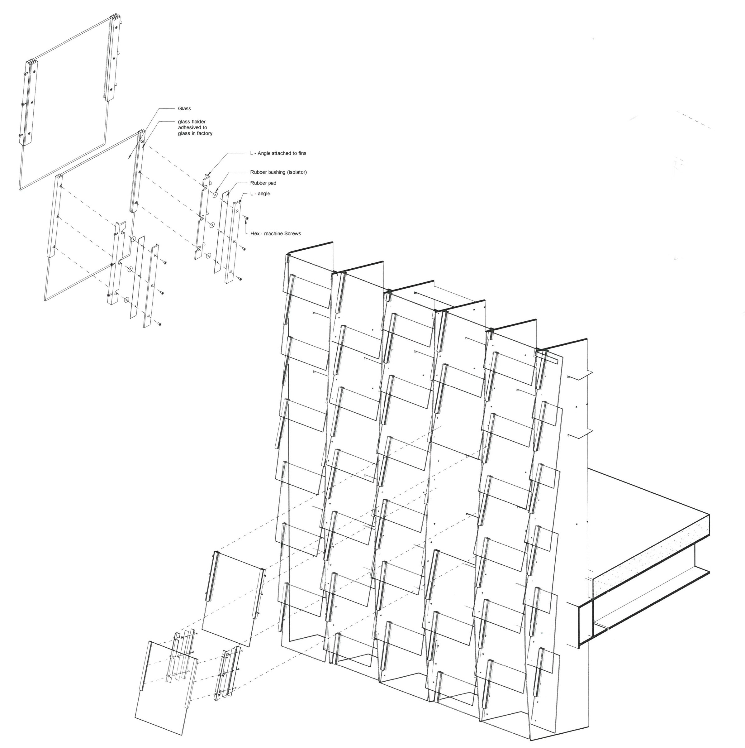
Parametric glass facadeParametric glass facade system driven by a Python generator. The script instantiates real Revit family panel objects, then aligns each instance by angle and rotation to produce a controlled field of glass panels across the elevation. Built as a repeatable workflow: rules in code, geometry in Revit.
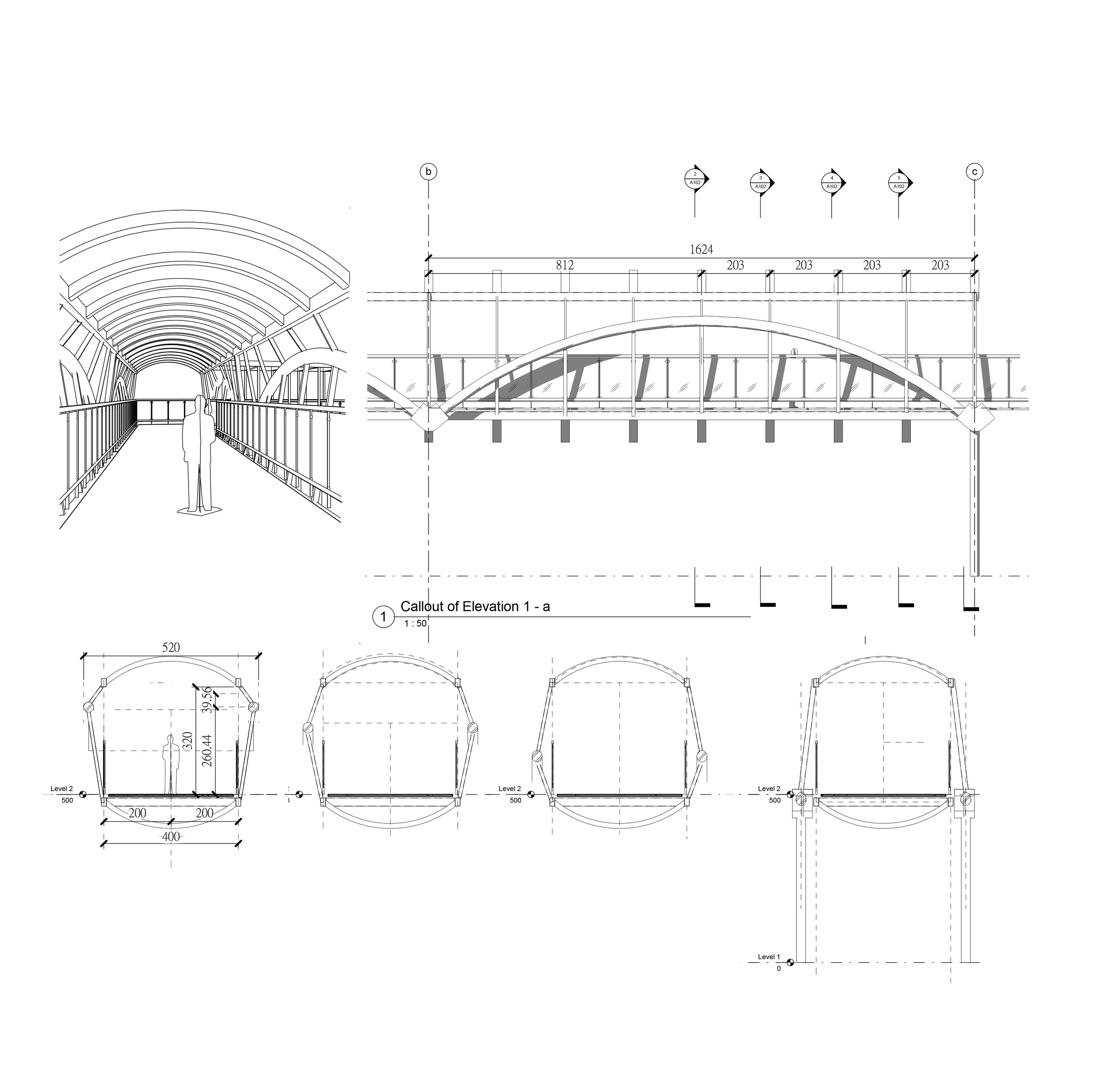
Parametric bridge studyRevit-based bridge study using a hybrid workflow of parametric modeling and custom families. The system generates a structural tube and the connective conditions between segments, keeping geometry editable while preserving constructible logic and repeatable detailing.
Parametric elevation & openingsThis elevation and its detail windows are built as a single parametric drawing in which one driving parameter governs the entire window geometry. Changing that single value regenerates the opening's shape and recomputes how it is cut out, propagating the change across the elevation and its linked details. The logic ties back to early AI-driven work, so dependencies resolve automatically instead of requiring manual redrawing. One edit therefore flows fluidly through the construction documents and the set updates itself.
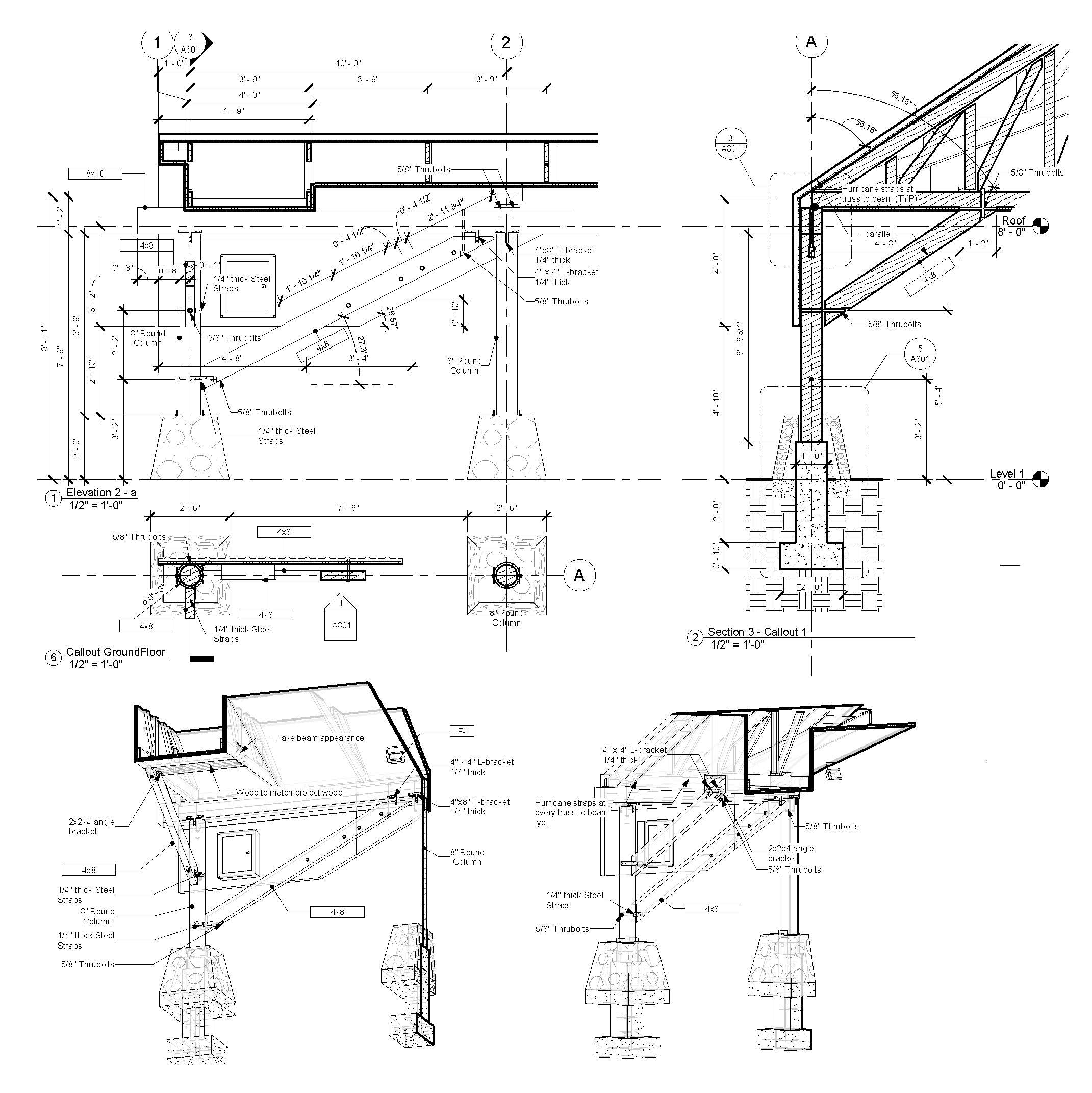
North Fork pavilion detailsNorth Fork Ranch community pavilion detail drawing built in Revit. Framing is developed through generative, rule-based methods, then verified and refined in a headed workflow by drilling down into a construction detail set that is buildable and repeatable.
Why nodes carry the design
A building fails at its weakest node. The concept lives or dies at the points where assemblies actually connect: parapet, sill, threshold. Each node is where intent meets gravity, water, and tolerance. Resolve one poorly and the whole graph reads the failure.
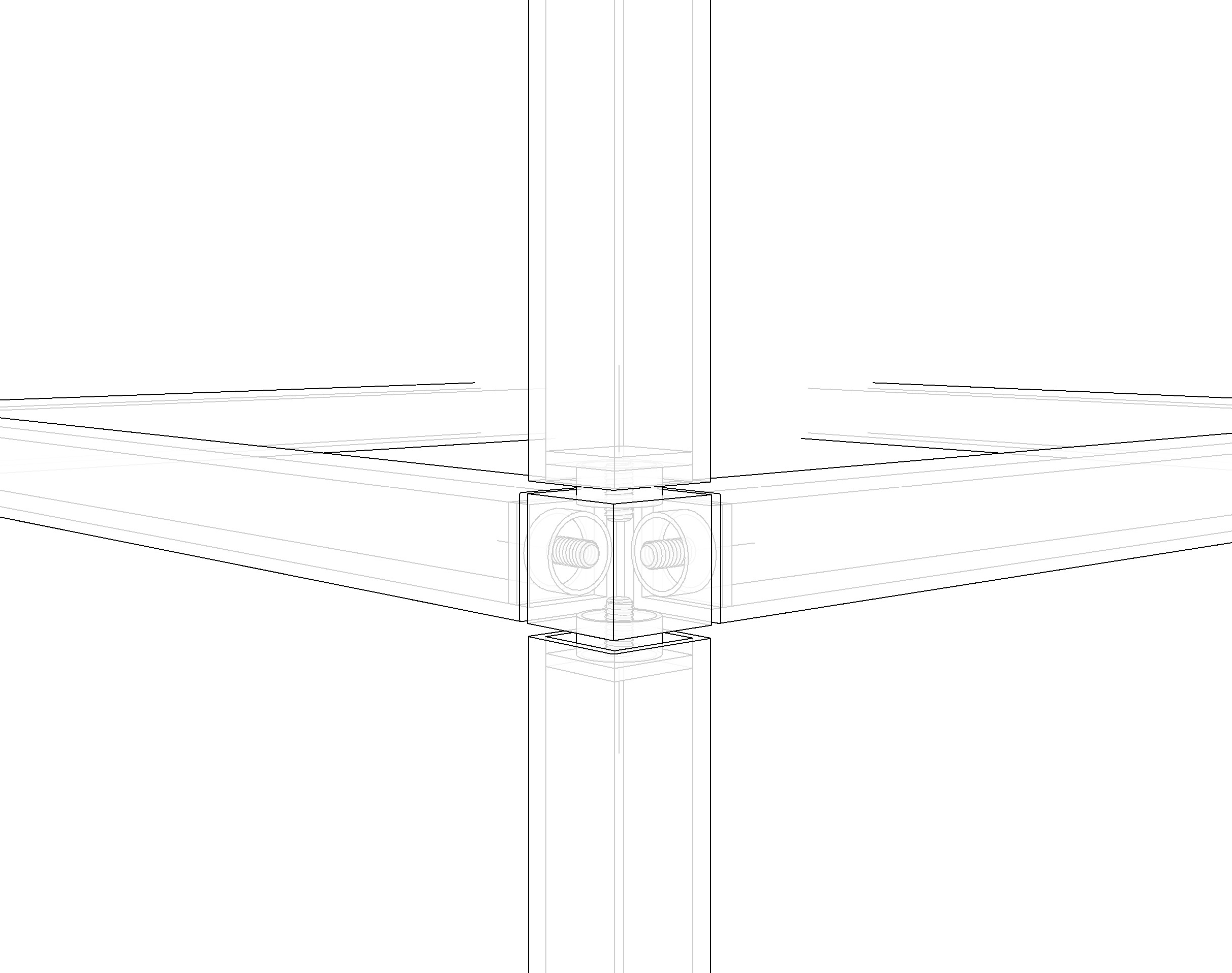
Modular corner pieceRevit-modeled modular corner piece designed for Iterative Studio. Combines sculptural presence with practical seating, scaling from an art installation to a loungeable, buildable structure through repeatable modules.
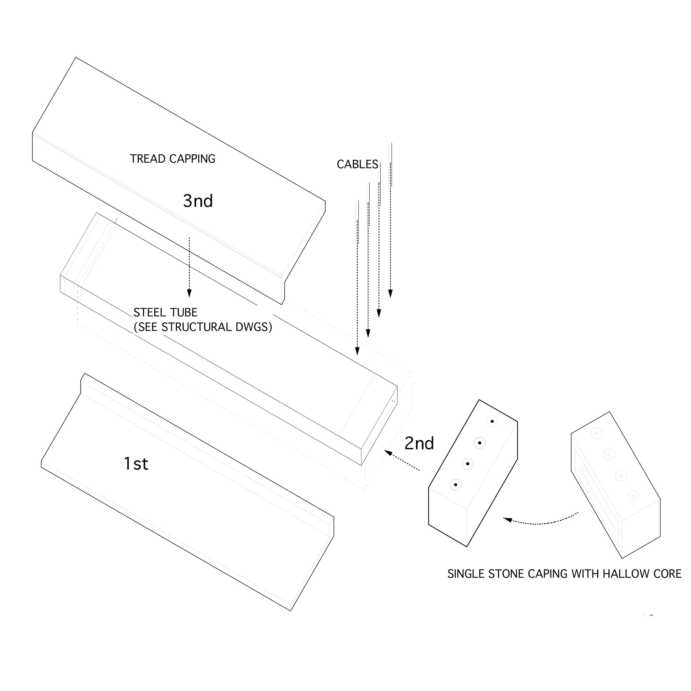
Legacy AutoCAD stair detailLegacy AutoCAD stair detail sheet built with Xrefs (early linked-drawing workflow, 10+ years old). Included as a proof of [i]'s technical depth: coordinated linework, callouts, and constructible detail resolution across referenced files.
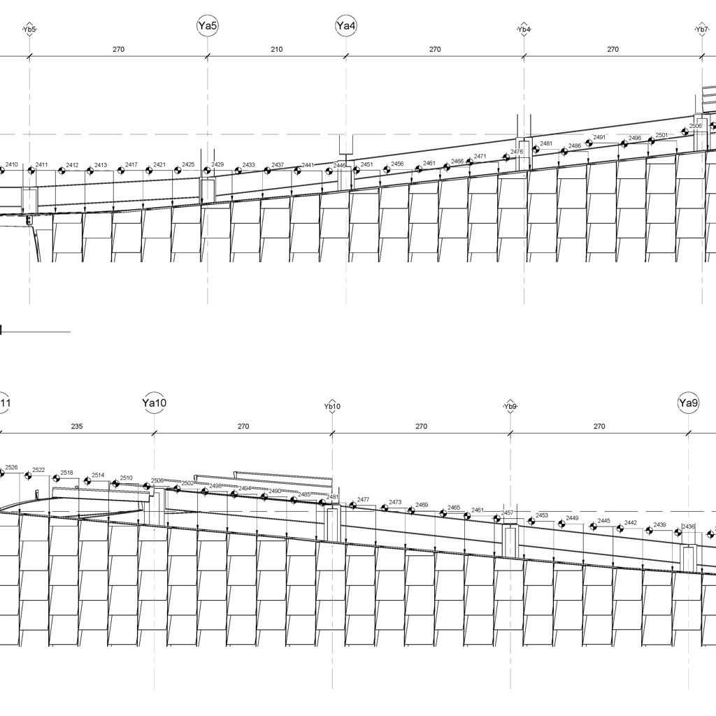
Facade setting-out gridThis detail is generated from a core Dynamo parametric model that rationalizes the facade's complex geometry. The script populates a structured point grid and computes the elevation (Z) of each node at ~100 mm spacing across the surface. These coordinates export directly as setting-out data, giving fabricators precise per-point reference values. Installation therefore tracks the model with no manual interpolation, preserving design intent.
Legacy AutoCAD Xref setLegacy AutoCAD construction document built with Xrefs: 2-4 externally referenced drawings are linked so updates propagate across sheets. Included as proof of [i]'s early multi-file coordination: a proto-generative drawing system for consistency, revision control, and scalable documentation.
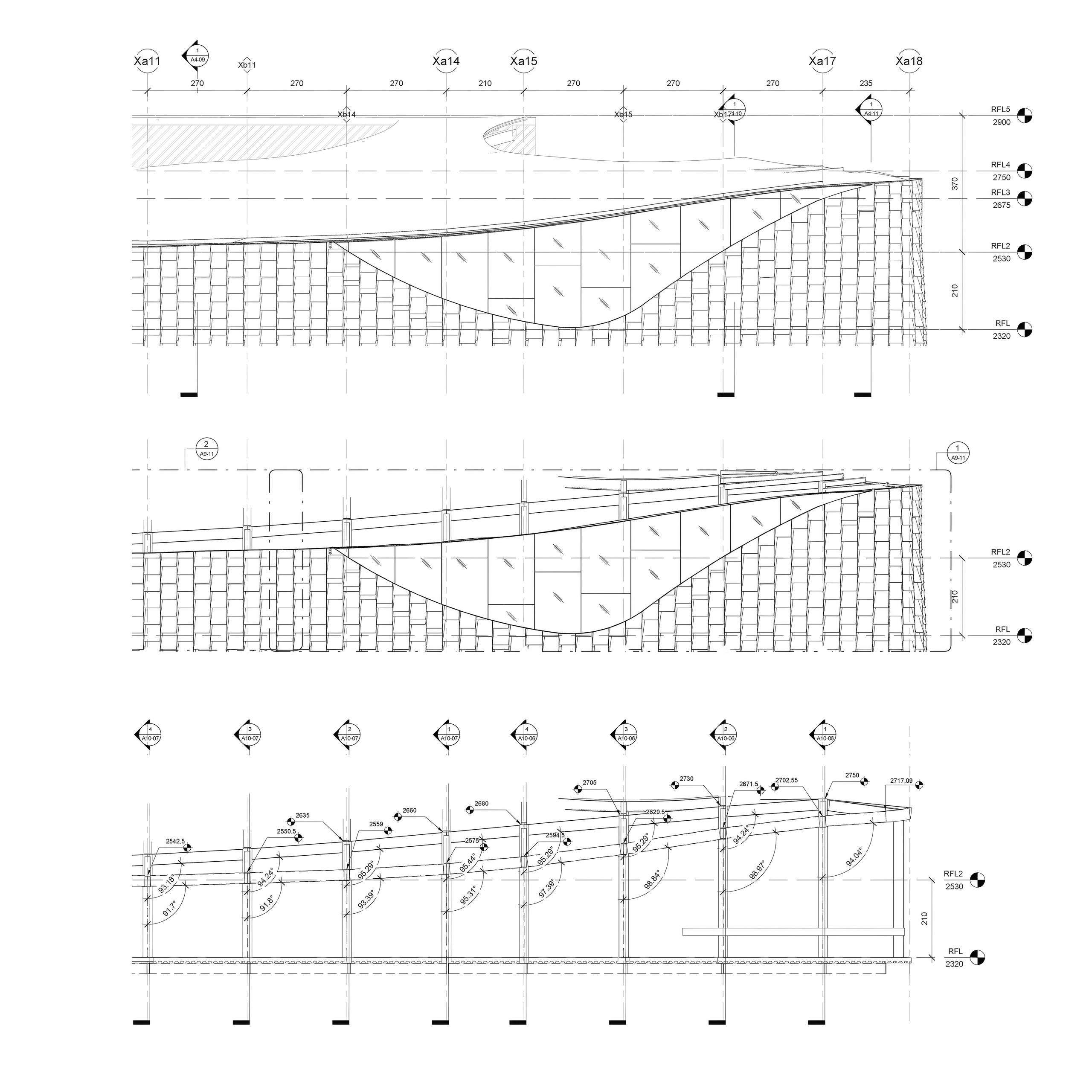
Facade, structure & openingsThree stacked views of the same facade zone: elevation, opening geometry, and the structural system below. Windows sit inside resolved detail parameters: change an opening's shape and the rest of the facade redraws with it. Structural beams within the zone follow the same drivers, so one parameter click updates both the envelope drawing and the framing it supports. Control points move up or down to soften curves or tune any element to the design; geometry, structure, and sheet stay one coordinated graph.
Where headless AI struggles
A model can generate one striking image. It cannot hold the gradual variance across hundreds of coordinated nodes, where each point shifts slightly with substrate, angle, and tolerance, yet must stay consistent with the whole graph. That accumulated, cross-referenced judgment is exactly what construction documents demand and what generation alone cannot keep honest. It is why [i] keeps a head in the loop.
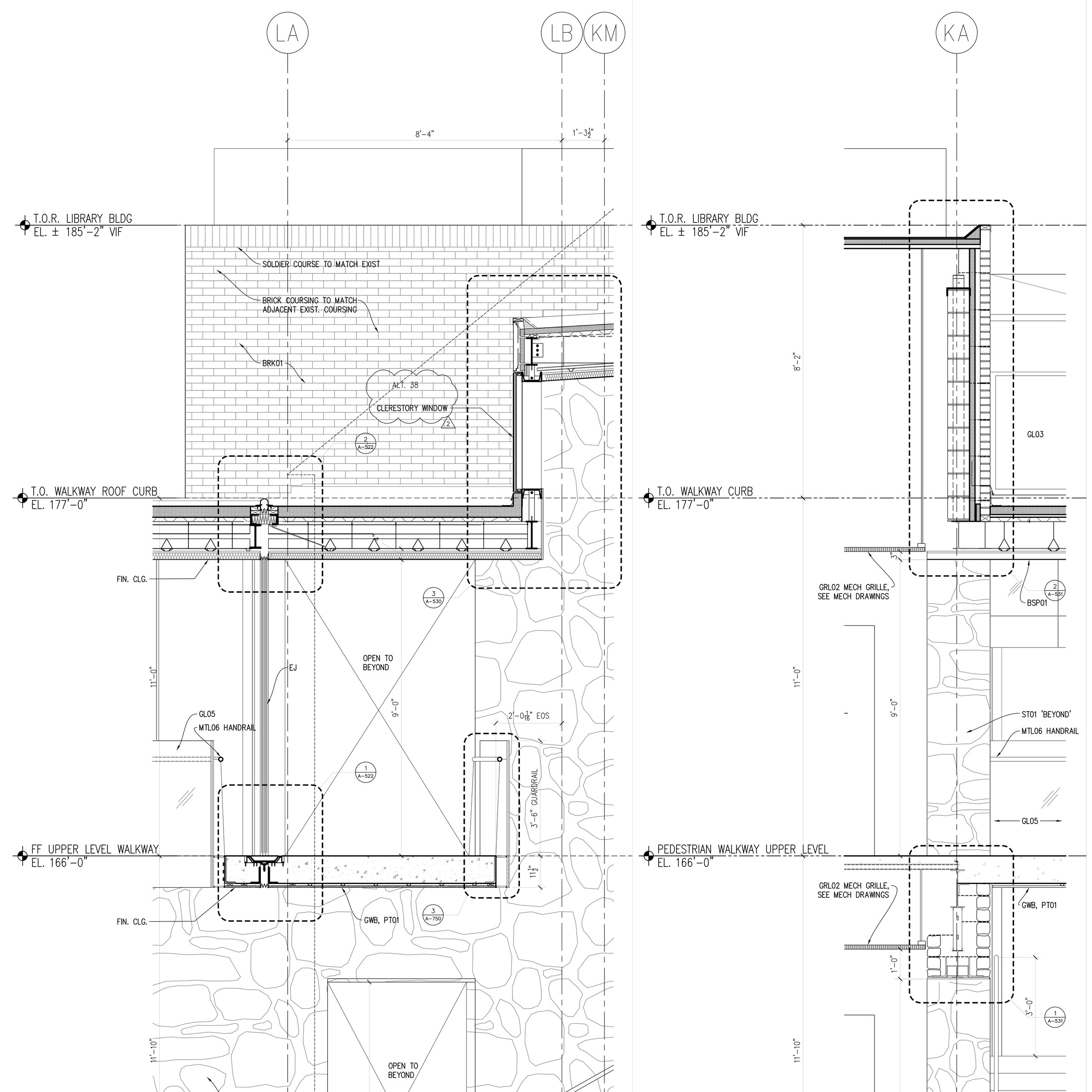
Legacy AutoCAD wall connectionLegacy AutoCAD wall connection detail showing core envelope control layers: waterproofing, fireproofing, and points where assemblies meet. Included as proof of [i]'s constructability focus, where waterproofing is treated as a primary design control that drives detailing, sequencing, and long-term performance.
Legacy AutoCAD axonometricLegacy AutoCAD axonometric (pre-3D) drawing. Uses classic axon/hand-drafting conventions translated into CAD to read as a 3D object on a 2D sheet. Included as proof of [i]'s ability to communicate spatial complexity clearly without relying on 3D modeling or rendering workflows.
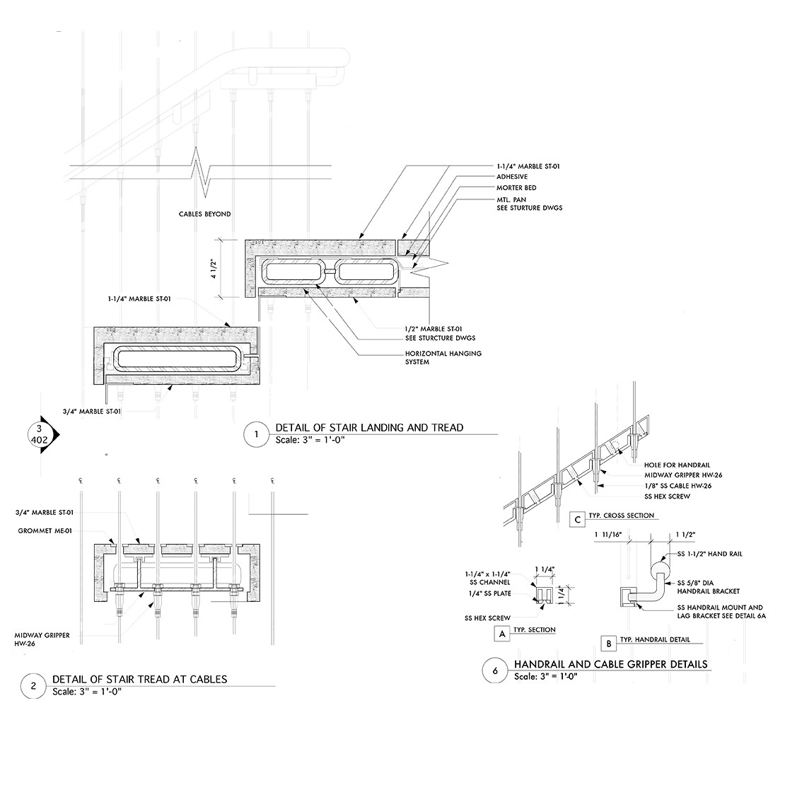
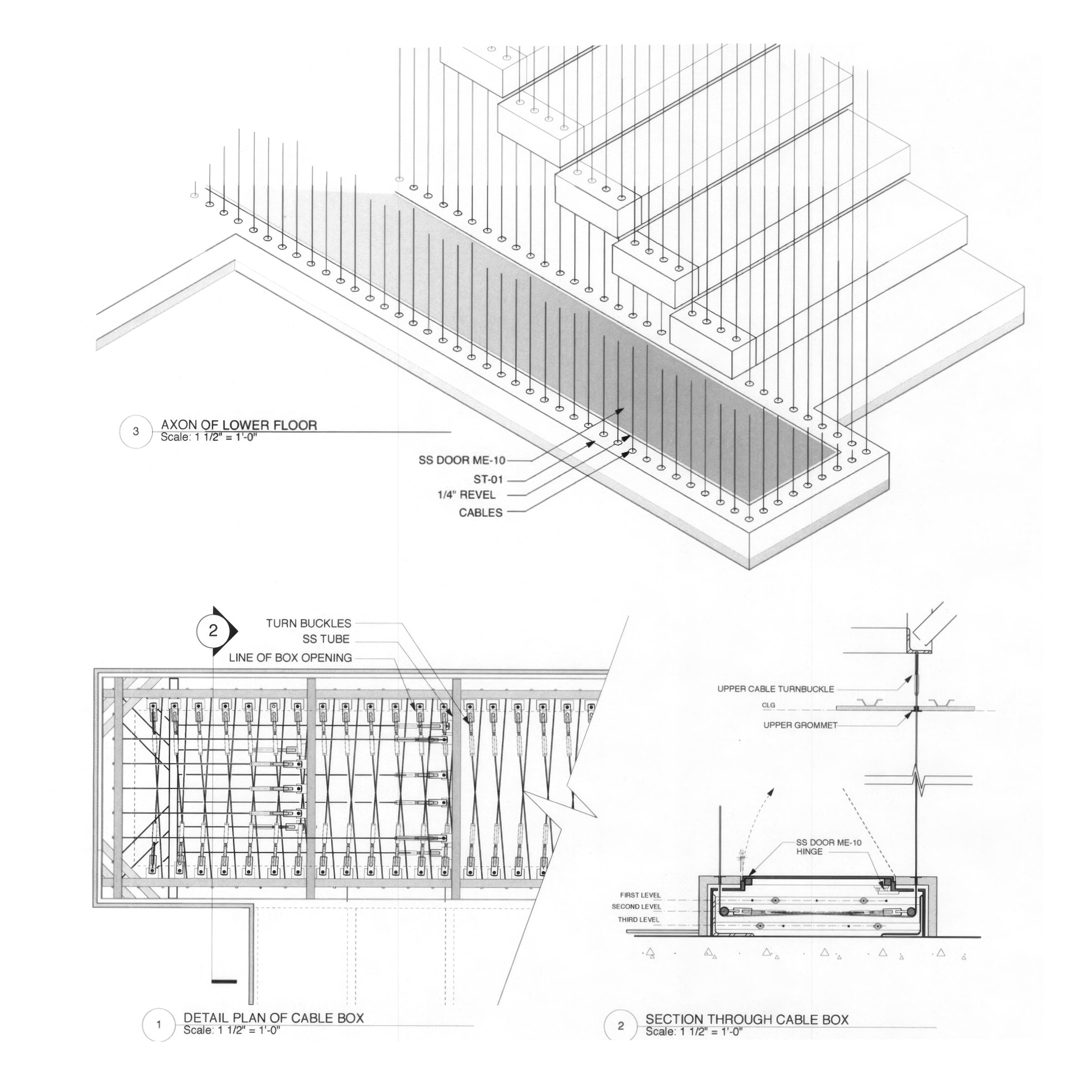
Legacy AutoCAD stair baseLegacy AutoCAD detail drawing: a fully 2D sheet that still communicates 3D logic for the stair base cable system (routing, anchorage, and clearances) using classic drafting conventions. Included as proof of [i]'s ability to resolve and document complex assemblies clearly without 3D modeling.
Rows of nodes are the proof
Renders persuade; nodes legitimize. The legacy sheets in this wall are the receipts: [i] was linking drawings through Xrefs before 3D modeling existed in practice, running proto-generative systems where one update propagated across the whole set. Parametric models extended that logic. Headed AI is its newest node. A wall of resolved points is evidence the idea was carried all the way to buildable, not stopped at the picture.